Installation of a Digitrax DZ123 in a Kato AC4400 N-Scale Model
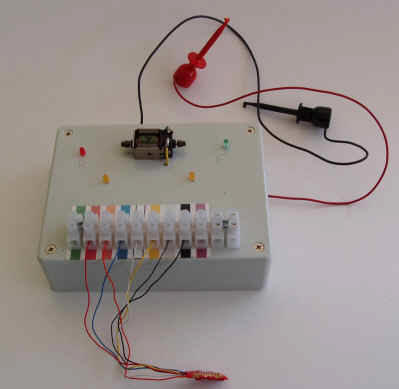
It is important to check the decoder before cutting wires or Digitrax will not replace it for free. I made a little test box myself using an old LifeLike motor and some cheap parts from a local electronic store.
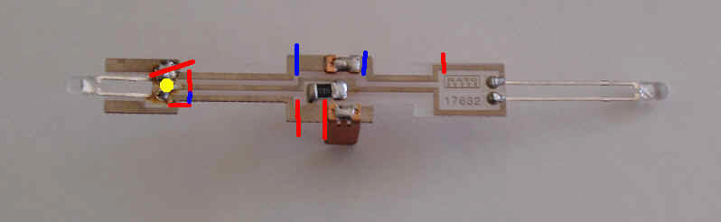
Using the new Kato's circuit board, the diode marked with a yellow dot has to be unsoldered first. To keep the diode in place while applying heat to the connection, I put an electric tape around the diode leads and the circuit board. I also tried to get rid of most of the solder. Next step is to cut the electric traces on the circuit board. The red lines are necessary cuts. Since the frames are very close to the traces, I also cut them where they could touch the frames and shorten out the decoder (blue lines). Now check if each solder spot is perfectly insulated.
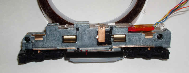
There is enough room for the DZ123 under the circuit board. I use a piece of Kapton tape to attach the decoder to the LED leads. Notice the electric pick up for the motor how it touches the frame, which is not very healthy for the decoder.
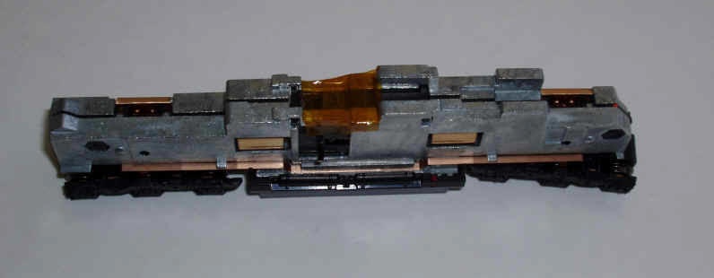
Although the AC4400 is DCC ready, there is one spot that could possibly shorten the circuit board. It is right above the electric pick ups for the motor and I used a piece of Kapton tape for insulation.
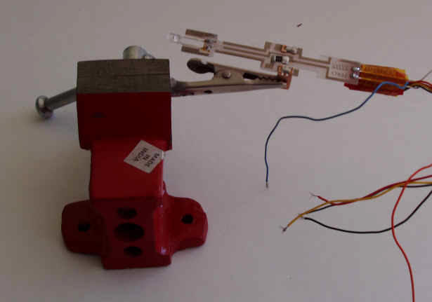
A $5 vise is perfect soldering device.
Since I use the resistor on the circuit board, a blue wire needs to connect the front LED with rear. Notice the blue wire is connected to the lower rear LED lead and the upper front LED lead. I do not provide any cut length for the wires since it is much easier to hold the wire to the soldering spot and cut them exactly as needed.
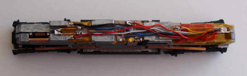
Keep the wires as short as possible since there is not much clearance under the shell.
If you have problems, just send me an e-mail helveticarr@aol.com
Enjoyed this web site, try this link as well www.engineshop.org